you are here [x]: Scarlet Star Studios > the Scarlet Letters > a new jig for radiusing
<< before
30fps - flicker textures
after >>
wishes & fishes
August 20, 2006
a new jig for radiusing
by sven at 8:36 pm
Before our vacation to Canada, I had started working out how to make my first steel armature. During the past few days I've made some new progress.
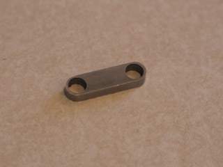
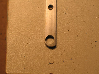
Above you see a "sandwich plate." A pair of these would sandwich two steel balls, making an "open hole double ball" joint. Rounding off the ends of the plate is called "radiusing." Figuring out how to do that rounding took a lot of effort. It's my big success for the day.
[The simple solution would be to hand-file the curve. However, I'm making this armature for show, and want it to look fancy. Figuring out how to do radiusing is also a good learning project, to help me get used to my new milling machine.]
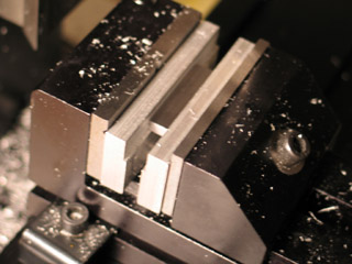
If you're going to drill holes through plates, then you need to put spacers underneath, so the drill bit doesn't cut into your milling vise. What I've done is cut a little .03" shelf into two pieces of aluminum. This is just enough room for supporting the 1/4" wide bar, while letting the 3/32" dia. drill bit pass through unhindered.
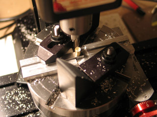
To hold the sandwich plate in place for radiusing, I needed a jig. My first attempt was successful -- but it was miserable trying to get the rotary table centered under the spindle, squaring the jig to the milling table, and clamping the jig down with step block hold-downs... Too fiddly, and the jig was liable to come loose whenever I unclamped a sandwich plate in order to put another in.
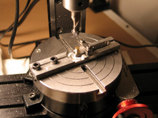
I modified the jig design, drilling holes in one side so I could use socket cap screws and T-nuts to clamp the jig directly to the rotary table. I also added two 4-40 screws on top of the jig, so a little bar could be screwed down to hold the sandwich plate in place. These changes made clamping much easier and more reliable...
...However, I didn't have the holes in the jig perfectly centered. Consequently, the jig was imperceptably angled on the rotary table. Turning the table amplified a small error; so rather than rounding off the plate's end, I got a wonky arc.
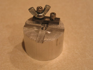
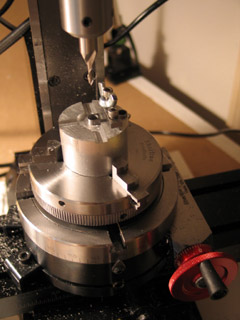
Friday night I finally had my "ah-ha!" moment. Most of the misery here has to do with getting the jig perfectly centered... Well, a lathe chuck is designed to get things perfectly centered -- and the rotary table came with an adaptor so you can attach a lathe chuck. A round jig should do the trick!
Saturday I went out to Metal Supermarkets and picked up a 1" length of 1.5" dia. aluminum rod. A little more than six hours later, I finished making the jig you see above.
A couple of things I've learned in the course of this project...
RPM for milling aluminum: usually 2500. RPM for milling 1018 steel with a 1/8" end mill: 1000. RPM for milling 1018 steel with a 1/4" end mill: 500.
Everyone says to take shallow cuts -- and they're right. When roughing out the radius, .03" cuts are appropriate. For the final passes, .0010" and .0005" passes are appropriate. Try to take too deep a cut and the jig might buck, the cutter could get stuck, and the accuracy will be bad. In fact, it's best to do your first passes with the cutter not even touching the work, just to make sure that you're not going to suddenly dig into an unexpectedly thick surface.
Working with backlash... If you're moving the XY table to the right and then reverse directions, there's a moment when you're turning the handwheel but the table isn't moving -- because the leadscrew has some play and hasn't grabbed hold yet. This is called "backlash."
Your measurements are only good when you're moving the table in one direction -- if you back up, backlash will introduce uncertainty. So, if you overshoot your mark, you have to back up past the backlash, and then go forward again.
I've got a digital read out (DRO) which can be set to accommodate for backlash -- but I've seen at least one online warning that adding and subtracting backlash to your measurements is an inaccurate method.
My current method for locating the spindle in relationship to something in the vise: I put a piece of 1/8" rod into the drill chuck and move it forward until I hit the edge of the vise... When I hit the edge of the vise, I zero-out the DRO. I back the spindle up a good ways and then, going forward, use the DRO to help me move the spindle to where I need it.
Oh! And I used a fly cutter for the first time. That's a rotating blade that can "quickly" flatten out wide surfaces (up to 2" wide).
I think -- knock on wood -- that I'm just about ready now to start working on the armature proper.
posted by sven | August 20, 2006 8:36 PM | categories: stopmo