you are here [x]: Scarlet Star Studios > the Scarlet Letters > how to make a brass ball-jointed armature (part 5 of 5)
<< before
how to make a brass ball-jointed armature (part 4 of 5)
after >>
neighborly
June 23, 2006
how to make a brass ball-jointed armature (part 5 of 5)
by sven at 9:05 pm
You've attached balls to rods, and you've made sandwich plates. So, all the parts for joints are ready. What's left is to create the chest, pelvis, and feet of the armature.
MAKING THE CHEST AND PELVIS
For this design, the chest and pelvis will each be made from segments of a 3/4" wide K&S strip. We'll solder onto these plates several of the ball-and-rod assemblies that we made earlier.
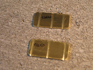
Step 1: Cut off two lengths of brass. I'm using 3/4" wide, .064" thick brass strip segments for the chest and pelvis of this armature. Depending on your design, a 1/2" or 1" wide strip could work just as well. I cut off 1.5" lengths from the original 12" long strip using the Dremel rotary tool.
Step 2: Round off the corners. Use the Dremel to round the corners of the rectangles you've cut. It's a kindness to your own hands, to not leave pointy scratchy parts. Also, it should help protect the puppet that you build on top of the armature from being torn.
Step 3: Make grooves. You're going to solder rods onto these strips. That task will be much easier if you first make grooves for the rods to sit in. After measuring and scribing guide lines, start the grooves by notching the edges of the strip with a triangle-shaped needle file. The edge notches make it easier to begin filing in a straight line. After you have a significant groove in place, round it out with the round needle file.
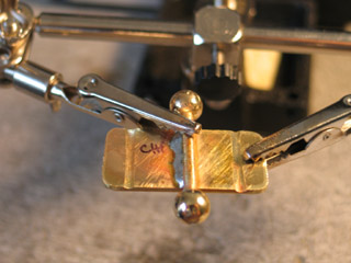
Step 4: Position your work piece in the "helping hands". Place one of your torso plates into the "helping hands" tool. One clamp should hold the plate up, while the other clamp holds a ball-and-rod in its groove.
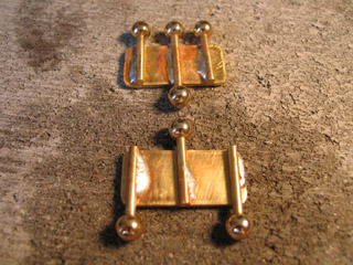
Step 5: Solder. The trick to soldering is that you apply flame to the metal that you are going to solder, never to the soldering wire itself. Let the heat of the brass do the work of melting your soldering wire. Apply flame to one side of a rod while holding a length of wire against the other side.
Step 6: Quench. Cool the work piece off before moving on to the next join. Squirt it with water from an eyedropper, and then use needle-nosed pliers to dunk it in a jar of water.
During the soldering process you may wind up accidentally frying one of the ball-to-rod joins. If this happens, refer back to the section on attaching balls to rods and fix the break.
MAKING FEET
It's crucial to make tie-downs in the feet of your puppet so that you can attach it firmly to the floor of your set. You have the option of drilling a hole in the foot of the armature and using a tap to thread it. That's a fairly elegant solution. Personally, I prefer to solder a hex nut onto the foot -- it just feels sturdier to me (particularly for larger armatures).

A very simple way to make a foot is to drill a hole in a foot plate, solder on a hex nut over the hole, and then solder on a rod-and-ball. If you go this route, it's useful to file a groove into the foot for the rod to sit in while you do your soldering.
Notice that with this design the ankle joint will actually rest on the ground. You'll want to "freeze" one of the balls in this joint with solder, so that the ankle has only one point of rotation.
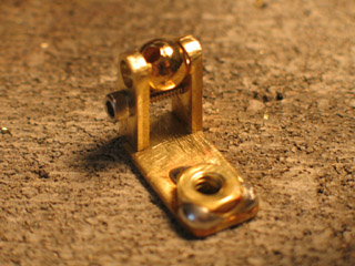
On the armature design that I'm demonstrating, I wanted to avoid having to freeze a ball in place. What I came up with is a sort of simple "step-block" joint. The basic idea is that a sandwich plate joint will rise vertically from the flat of the foot. One sandwich plate will be soldered in place, the other will move freely.
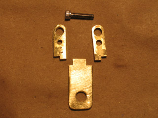
For the flat part of the foot, I used brass strip that was 1/2" wide and .064" thick (1/16"). This particular foot is one inch long. The hole for the tie-down screw is 7/32" wide. The nut that will go on top of it is size 10-24. The sandwich plates each have little notches at their bottom that will fit into notches in the flat of the foot. The space between the sandwich plates is 7mm wide.
Use the Dremel rotary tool to rough-out the notches. Use a triangle needle file to make the notches as accurate as you possibly can.
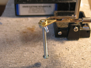
When you solder the brass nut onto the flat of the foot, be sure to first give both parts a light sanding with fine-grit sandpaper. This will help remove oils from the surface of the brass and help the solder adhere better.
Hold the nut in place by screwing the tie-down screw up and through it from beneath the foot plate. Hold the work piece in position for soldering using the "helping hands".
Solder on three sides of the nut. Remember that the trick to soldering is to apply flame to the metal that you're going to solder, never to the soldering wire itself. Each time you solder a face of the hex nut, apply your flame to a part of the foot plate that is on the opposite side of the nut.
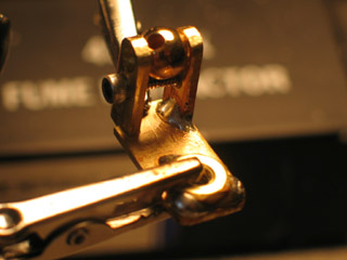
The best way to hold the sandwich plates in place when you attach them to the flat of the foot is to simply put a spare ball in and tighten the joint onto the foot's sole. Use the "helping hands" to hold the foot in place while you solder. Solder only one plate in place: the one with the threaded hole. Heat the ankle area from the outside of the joint as you apply solder to the inside.
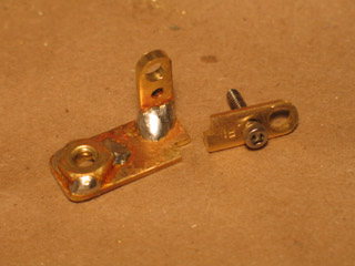
Here's the completed foot. Notice how one plate is fixed in place, while the other is able to move freely.
This is a very workable foot design... It's worth noting that on a more professional armature there would typically be a hinge in the middle of the foot. This is so a puppet could stand on its toes -- or walk heel-toe-heel-toe, rather than just landing flat on the foot each time it takes a step.
FINAL ASSEMBLY
You've built everything that you need for your brass ball-jointed armature: "open hole double ball" joints, torso plates, and feet. Place the sandwich plates around the appropriate balls, and tighten the 4-40 screws.
The project looks complete -- but you're not done quite yet.
Now that the armature is all together, spend some time playing with it. (...As if you could keep your hands off of it!) As you're twisting the limbs, it's quite likely that at least one of the balls will come loose from its rod. That's OK -- sometimes joins are weak. Better to discover it now, instead of later when you're actually animating. Review the section on attaching balls to rods and fix the break.
Test the armature again. If nothing breaks this time... Then you're DONE! Congratulations!!
OTHER RESOURCES
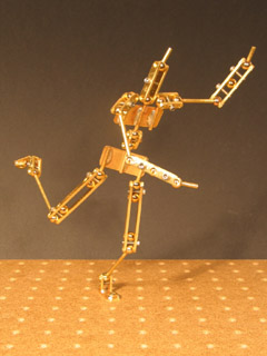
This essay is intended to fill a gap in the array of online armature tutorials that are currently available. On the one hand, you have very simple designs that use aluminum armature wire with epoxy putty for bones: e.g. by Mike Brent and by Nick Hilligoss. On the other hand, you have designs with “open hole double ball” joints that are made on a drill press: e.g. by Lionel Ivan Orozco, by Charles Hamper, and by limanima.com. This brass ball-jointed armature falls in-between those two kinds of designs. It is meant for animators who want to move up to making metal-jointed armatures, but who aren't yet ready to purchase big machines that need to be bolted onto a workbench.
For myself, this project is partly a way of taking baby-steps toward making truly professional armature designs. If that is your goal as well, I believe making steel armatures on a drill press (or mill and lathe) will come more after having done this project.
Even if it's not your ambition to build more sophisticated armatures, this tutorial may still be of some use. My hope is that by illustrating nearly every step of the construction process, you will be left with a very physical sense that you could make one of these things with your own hands. You may choose not to go to the effort -- but at least the process won't seem mysterious and beyond the realm of possibility.
Whichever way you go -- good luck!
Leap from here to...